Showing posts with label Spoke Length Calculator. Show all posts

Wednesday, July 24, 2013

Rims and Spokes

Now that the hubs are rebuilt I'm ready to starting lacing up some new wheels for the 1953 Sports.  The original 26 x 1-3/8" Raleigh Patent Rims which are commonly referred to as Westrick rims were rusted beyond use.  Most classic three speeds use a Westwood; Endrick; or Westrick type rim.

Westwood rim, these are intended to be used with rod-brakes, the brake pads bear against the raised center section.  They do not have side faces for caliper type brakes.
Endrick rim, these can only be used with caliper type brakes, there is no raised center section they can not be used with rod-brakes


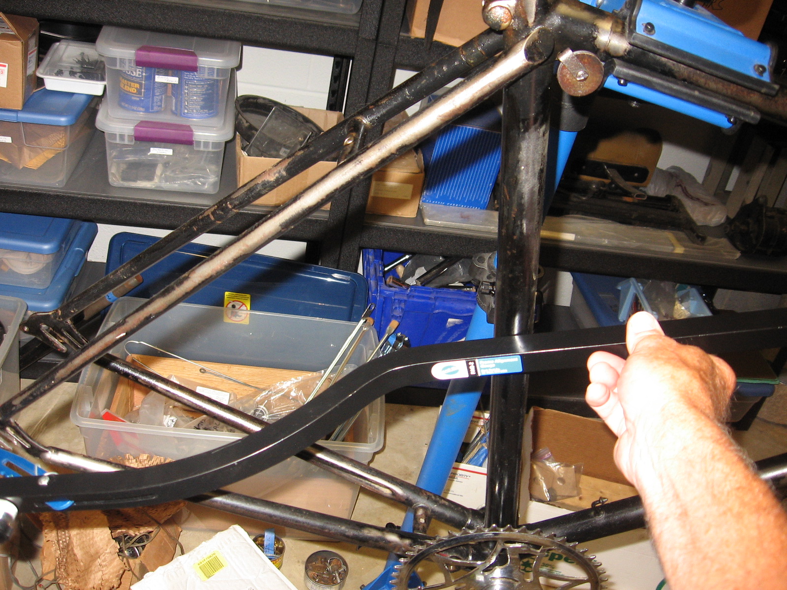
Raleigh Patent rims, A.K.A. Westrick, these are a cross between Westwood and Endrick rims.  They have a raised center section so rod-brakes can be used as in this picture.  You can also see they have a side face for caliper type brakes.

That ugly sticker just peels off

I will be replacing the rusted steel "Westrick" rims with Sun CR-18 alloy rims.  If you want to maintain complete originality replacement Westrick rims are usually easy to find.  I wanted to try these rims for their lightness and better braking, especially when wet.  When ordering new rims you must know the Bead Seat Diameter (BSD) of the rim.  For many classic three speeds using 26 x 1-3/8" tires this is 590mm (sometimes is referred to as 650A), but be careful there are some that have a BSD of 597mm.  The 1953 Raleigh Sport rim is 590mm.

I've also decided to use new spokes with the CR-18 rims.  When building wheels with new rims and spokes you also need to know the Effective Rim Diameter (ERD) of the new rim in order to calculate the proper spoke length for the wheel.  There are several ways to measure ERD, search on-line and find one you are comfortable with, most rim manufactures also publish this dimension, I prefer to measure it using the actual rim I'm building with.  I measured the original Westrick rims to have a ERD of 576mm, and the new CR-18 rims measured 578mm.  In this case there is very little difference between the two so the original spokes would  have been useable assuming I used the same number of spoke crossings.  There is an advantage to using the old spokes if you can because they are a better fit with the thin flanges used on the Sturmey-Archer (SA) hubs.  Modern spokes are designed for thicker hub flanges.  If you use modern spokes in the thin flanges of  a SA hub, you will need to use spoke washers to take up the extra space under the spoke head.

In addition to the ERD, most on-line spoke length calculators require measuring the diameter of the spoke hole circle on each flange, flange spacing center to center, number of spokes, and the number of spoke crossing you will be using, (2X, 3X, 4X, etc.).  I made a simple stand from a scrape piece of 2 x 4 and metal plate, with a 13/32" hole drilled, so the hub can stand upright on its locknut to facilitate obtaining hub measurements.


After you obtain your rim and hub measurements find a on-line spoke calculator you like and enter the input values, I usually use this one www.wheelpro.co.uk/spokecalc .  In my case using a CR-18 rim, 3X crossing, and a 40 hole AW hub, with 12mm spoke nipples, the spoke length calculated was 272.2 mm for the left flange, and 271.7 for the right.  I rounded these to 272mm and ordered 40 272mm spokes.  The spoke length for the front Dynohub using 3x crossing on left flange (small), and 2x crossing on the Dyno side (large flange) and a 32 hole hub, the length calculated was 282.8mm for the left, and 256.3mm for the right.  I rounded the left to 282mm (only even size lengths available), and the right side to 256mm.  I ordered 18, 282mm, and 18, 256mm spokes for the Dynohub.

Once the spokes and nipples are received I can start building the new wheels for the 1953 Sports.  There are many on-line sources for information on wheel building, find one your comfortable with and start lacing.

Please share your thoughts and experiences.

Monday, July 15, 2013

Adjusting Chain Line on the Sturmey Archer AW hub


The 1953 Raleigh Sports Tourist I’m in the process of refurbishing was originally equipped with an enclosed chaincase.  Unfortunately; during its previous history someone removed the lower portion with a hacksaw.  Finding an original chaincase complete with all the parts can be difficult and expensive.  I opted to purchase a repo chaincase from Yellow Jersey; however, fitting this chaincase to the Raleigh required some careful tweaking (bending) and patience (maybe a separate article).

There is very little clearance within the chaincase; determining and setting proper chain line is important to keep the chain from rubbing inside the case. Chain line is the path the chain follows from the front chainwheel to the rear sprocket; ideally this path should be parallel with the centerline of the bike.  Proper chain line will minimize sideward stress on the chain, drive-train noise, and wear.   Before determining the chain line, alignment of the rear triangle to the centerline of the bike (head tube/seat tube) should be checked and corrected (pic).  This will insure that the hub and dropouts are centered with the frame.  This can be accomplished with an alignment tool or by running a string from one rear dropout , around the head tube, and back to the other dropout , then measuring the distance of the string from each side the of seat tube, the distance should be within a couple of mm of each other.


Determining chain line requires measuring how far the front chainwheel teeth are from the centerline of the bike (seat tube), then comparing this to the distance the rear sprocket teeth are from centerline of the AW hub, this assumes the rear dropouts have been aligned to the centerline of the frame.  To measure the front chain line measure how far the center of the chainwheel teeth are from the center of the seat tube. Accurately measuring to the center of the seat tube can be difficult; I usually measure to the edge of the seat tube, then adding to this ½ the diameter of the seat tube.  In my case the distance from the chainwheel teeth to the edge of the seat tube was 28.66 mm., The diameter of the Raleigh seat tube measured 28.59 mm, the seat tube center is 14.3mm (1/2 of 28.59), adding this to this the distance the chainwheel teeth are from the edge of the seat tube (28.66 mm) results in a front chain line of 42.96 (14.3 + 28.66).  The rounded front chain line is 43mm.


To determine the rear sprocket chain line requires measuring the Over-Lock nut Distance (O.L.D.) of the AW hub (pic), dividing by 2 to determine the hub centerline, then subtracting from this result the distance the sprocket teeth are from the right hand side axle locknut.   It’s important to note that the O.L.D. can vary among AW hubs depending on how many spacing washers (Sturmey Archer Part HMW-129), cone lock washers (HMW-147), cone locknuts (HMN-132) or any other washers, nuts etc. that have been added or removed from the hub axle during its history.  The O.L.D is only affected by those axle components that reside between the rear dropouts.  Washers, spacers, and nuts etc. on the outside of the dropouts do not affect the O.L.D..    According to original Sturmey Archer service manuals the AW hub was delivered from the factory with one cone locknut and one spacing washer on the left hand side.  On the right hand side there should be one cone locknut, one cone lock washer, and no spacing washers.   In this configuration the O.L.D. from the factory was 4-5/16” or 109.5 mm.  This is why most 3-speed rear dropout spacing is 110mm.  In addition to being able to adjust the AW hub O.L.D. by adding/removing spacers, the position of the sprocket on the axle can also be changed.  Assuming the sprocket is a reversible (dished) three spline type, it can be flipped to move the sprocket teeth inward or outward as necessary by approximately 3mm.  The three spline sprockets are retained by a sprocket circlip (HSL-721), and two sprocket spacing washers (HMW-127).  Each sprocket washer is approximately 1.6 mm thick.  Both can be position on either side of the sprocket, or one on each side to move the sprocket in increments of 1.6mm along the axle.  You must always use two spacing washers so the circlip will properly seat in the driver groove securing the sprocket in place.  Reversing the sprocket or rearranging the sprocket washers will not change the O.L.D. but will change the rear chain line.

Before rebuilding the 1953 AW hub I noted the original location of all spacing washers, locknuts and washers and sprocket orientation.  In my case, the hub had spacing washers (HMN-129) located on both sides of the axle; normally there is only one located on the left side; normal cone locknuts on both sides; and normal cone lock washer on the right.  The dish of sprocket was located inward with spacing washers (HMW-127) on either side.  This configuration resulted in a O.L.D of 113.36 mm (pic).  I then measured the how far the centers of the sprocket teeth were from the right side locknut, the distance was measured to be 18.70 mm.  The rear chain line can now be calculated as ½ of the O.L.D. less the distance of the sprocket teeth from the right side lock nut.  113.36/2 – 18.70 = 37.98, or rounded to 38mm.  This represents how far the rear cop teeth are from the centerline of the frame.  Comparing the rear chain line of 38mm, to the previously calculated front chain line of 43mm shows the rear chain line needs to be moved outward 5 mm.


In order to accomplish this, I removed the extra spacing washer (HMW-129) from the right side of the hub axle, this moved the chain line approximately 2.5mm to the right, I also reversed the sprocket so the teeth were oriented outward by approximately 3 mm, I did not change the original location of the sprocket spacing washers, one on each side of the sprocket.  After these changes the O.L.D. now measured 110.40 mm, and the sprocket teeth were now 12.03 mm from the right side locknut.  Re-calculating the new rear chain line resulted in 110.40/2 - 12.03 = 43.17, rounded to 43mm, now matches the front chain line.  In actual practice adjusting the AW chain line is not nearly as complicated describing it in writing.

The original steel rims and spokes on the 1953 Raleigh were rusted beyond use.  I will be replacing the rims with alloy Sun CR18’s rims and stainless steel spokes.  Now that I have established the final O.L.D. for the rebuilt AW hub, I can order the proper length spokes, since the hub O.L.D. is one input required for most spoke length calculators.
Please share your thoughts and experiences.